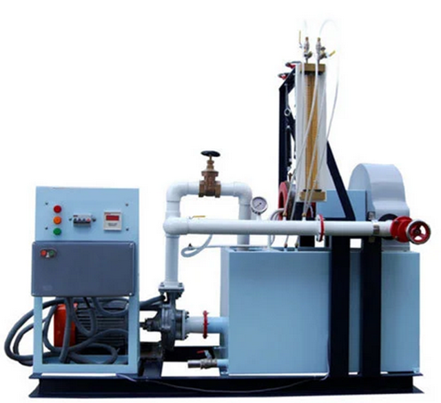
Flow Meter Demonstration Apparatus
The equipment consists of a Venturi meter, variable areameter and orifice plate, installed in a series configuration to permit direct comparison. A flow control valve permits variation of the flow rate through the circuit. Pressure tapings are incorporated so that the head loss characteristics of each flow meter may be measured. These tapings are connected to an eight tube manometer bankIncorporating a manifold with air bleed valve. Pressurization of the manometers is facilitated by a hand pump. The circuit and manometer are attached to a support framework which stands on the working top of the Hydraulics Bench. The bench is used as the source of water supply and for calibrating volumetrically each flow meter.
EXPERIMENTS
- Calibrating each flow meter using the volumetric measuring tank of the bench.
- Application of the Bernoulli equation for incompressible fluids.
- Direct comparison of flow measurement using a Venturi meter, orifice plate and rotameter.
- Comparison of pressure drops across each flow measurement device.
- Comparison of pressure drops across a sudden enlargement and a 90° elbow.
Features
- Shows the typical methods of measuring the flow of an essentially incompressible fluid (water).
- It also shows applications of Bernoulli's equation.
- Students are able to measure flow using a Venturi meter, an orifice plate meter and a rotameter.
- Bernoulli's equation works for each meter.
- Losses in a rapid enlargement and a 90- degree elbow will be found.
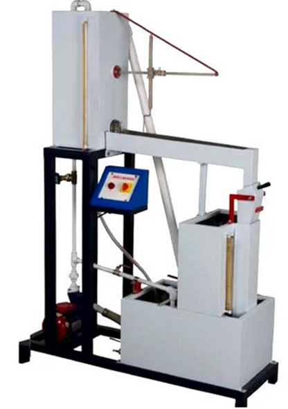
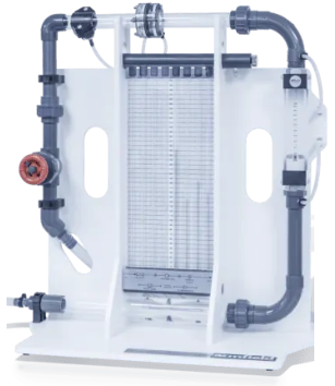
- It is having a horizontal pipe that include a Venturi meter, orifice plate and pressure tapping’s.
- An elbow connects the pipe to a rotameter (gap-type flow meter) with further pressure tapping’s.
- All pressure tapping’s connects to manometers held on a vertical panel behind the pipe work.
- The manometers measures and show pressure distribution against a calibrated scale.
- Water from a digital hydraulic bench flows through the Venturi meter, through a sudden enlargement, a settling length and the orifice plate.
- It also flow around the elbow, through the rotameter, then a flow control valve, finally returning to the hydraulic bench.
- The control valve will be downstream.
- To adjust the datum water level in the manometer tubes, a hand-pump is connected (will be supplied) to the valve above the manometer tubes.
TECHNICAL DETAILS
|
Number Of Manometer Tubes |
Minimum 11 Manometer tubes Manometer is scaled to 0 to 380 mm. |
|
Orifice Plate Diameter |
Minimum 20 mm diameter with corner tappingsmanufactured to BS1042. |
|
Variable Area Meter |
Scaled 0 to 210 mm. Includes calibration chart for 0 to 35 litres per minute. |
|
Venturi Dimensions
|
Material: Clear Acrylic, Upstream diameter: 26 mm ± 0.05 mm, Throat diameter: 16 mm ± 0.02 mm, Downstream diameter: 26 mm ± 0.05 mm, Upstream taper: 22.6° Downstream taper: 6.4° Coefficient of Discharge: Nominally 0.93 |
|
Sudden enlargement |
26 mm to 51.9 mm |
|
Maximum flow |
28 litres per minute |
|
Required accessories |
Will be supplied with all necessary pipe clips, tubing and printed operation manual. |
|
Drawing & dimensions of Venturi meter and Orifice meter will be silk-screened on to base plate. |
|