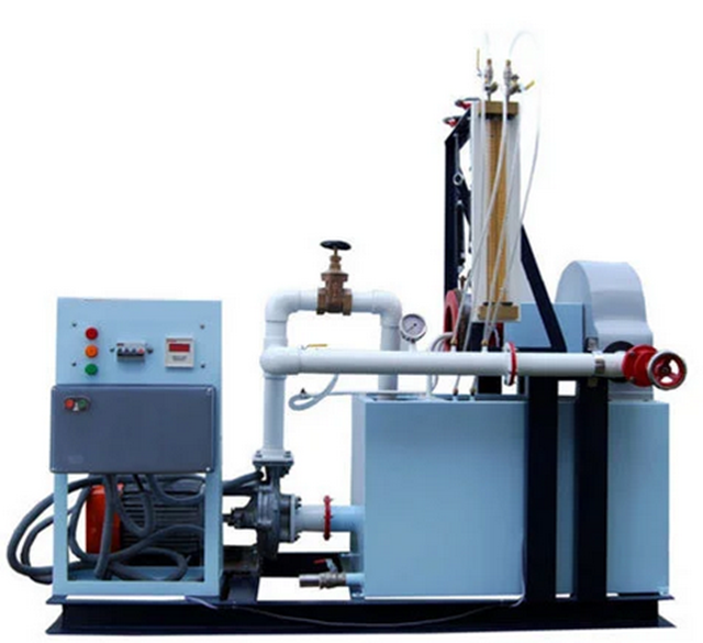
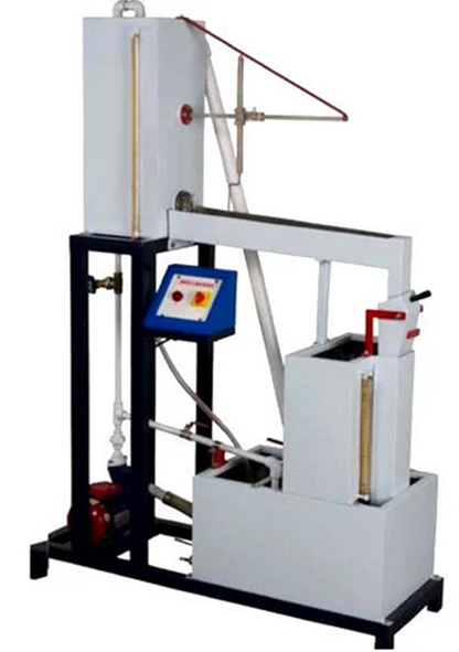
Losses Due to Friction in Pipe Lines Apparatus
The setup consists of 3 pipes of different diameters and materials, which are connected in parallel. Pressure tapings are provided on each pipe to measure the pressure losses with the help of a Differential Manometer. Control valves are fitted on each pipe, which enables to use one pipe at a time for experiment. Present set-up is self-contained water re-circulating unit, provided with a sump tank and a centrifugal pump etc. Flow control valve and by-pass valve are fitted in water line to conduct the experiment on different flow rates. Flow rate of water is measured with the help of measuring tank and stop watch.
Technical Specification :-
| Pipe test section |
Three pipe line Diameter : 1/2" inch , 1" Pressure taping length: 1meter Material G.I, SS.
|
| Pressure measurement |
Pressurized differential pressure manometer
|
| Pipe |
GI, SS Pipes
|
| Sump Tank Capacity |
65 Liters. (Stainless steel material)
|
| Measuring tank capacity |
30 Liters. (Stainless steel material) fitted with Piezo-meter Tube scale.
|
| Water Circulation |
1/2 HP pump.
|
| Stop watch |
Electronic.
|